
Dissolved Air Flotation in Wastewater: Optimizing Treatment Efficiency
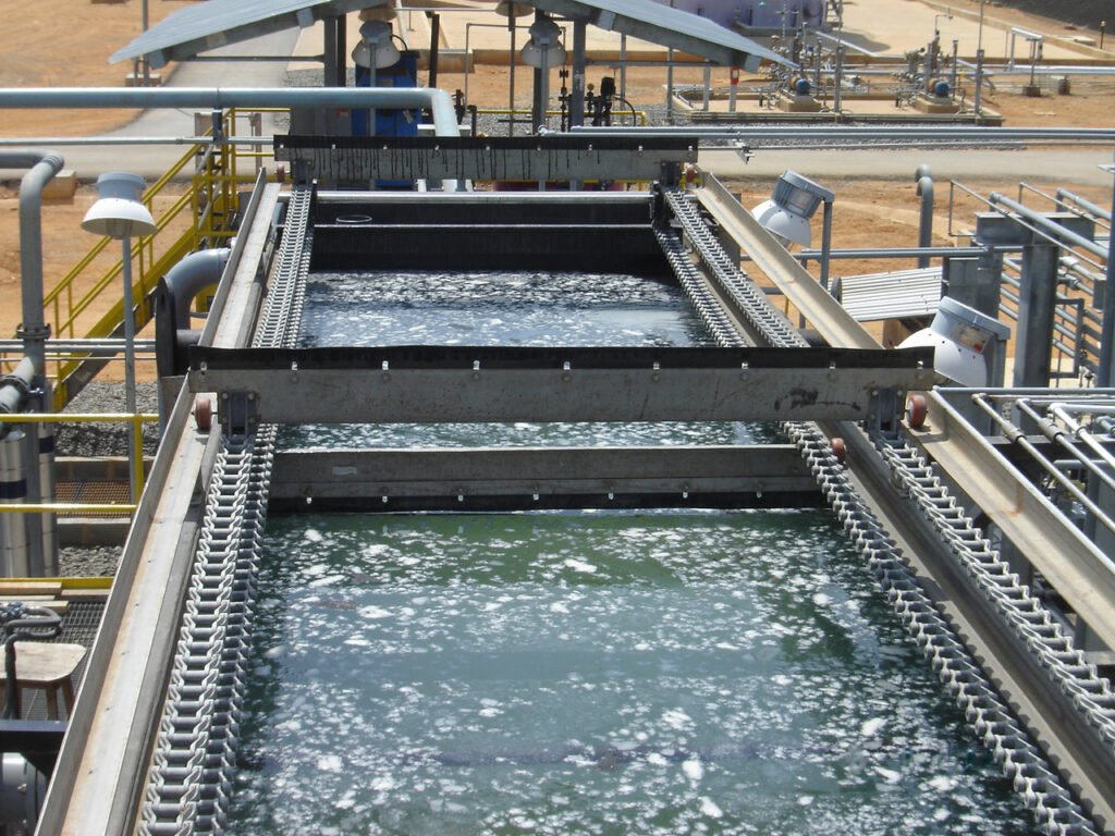
Dissolved air flotation (DAF) is a water treatment process that clarifies wastewater by the removal of suspended matter such as oil, grease, or solids. The removal is achieved by dissolving air in the water or wastewater under pressure and then releasing the air at atmospheric pressure in a flotation tank or basin. The released air forms tiny bubbles that adhere to the suspended matter, causing the suspended matter to float to the surface of the water where it may then be removed by a skimming device.
Central to the process is the introduction of air into water at high pressure. The pressurized water then goes through a pressure reduction valve where it is released into the flotation tank, and the air becomes supersaturated and precipitates out of the water to form microbubbles. The microbubbles attach to floc in the wastewater, causing it to rise to the surface, forming a layer that can be mechanically skimmed off. This technique is widely used in treating industrial wastewater streams that contain oils, greases, and other forms of suspended solids.
Within primary treatment, DAF occupies the position that gravity separation cannot fill. Conventional clarification depends on solids being denser than water and settling at a predictable rate, which fails precisely where it matters most: oily wastewater, buoyant or neutrally buoyant solids, light biological floc, and algae-laden water all settle poorly or not at all. DAF inverts the problem by attaching microbubbles to those solids and floating them out, achieving separation in minutes where gravity would need hours and might never succeed. That inversion is the whole basis for selecting it, and it also explains its cost, since generating and dissolving the air is what the plant pays for.
Key Takeaways
- DAF is a treatment process that clarifies wastewater by removing suspended matter.
- The process relies on supersaturated air bubbles to lift suspended solids to the surface.
- It is an essential step in industrial wastewater treatment for removing oils and greases.
Principles of Dissolved Air Flotation
Dissolved Air Flotation (DAF) is a water treatment process that clarifies wastewater by the removal of solids through flotation. Air is dissolved into water under pressure and then released, causing small bubbles to adhere to solid contaminants, thereby lifting them to the water surface for removal.
The configurations below differ in one respect: where and how the air is dissolved and released relative to the main flow. That single decision determines energy consumption, floc shear, bubble distribution, and equipment footprint, which is why the choice among them matters more than the differences in tank geometry.
Full Flow DAF
Full Flow DAF systems are designed where all the water is treated by induced air bubbles. In this set-up, pressurized, air-saturated water is injected directly into the influent, causing the suspended solids to rise to the surface for skimming.
Pressurizing the entire influent stream means the saturation system, pump, and pressure vessel must all be sized for full flow, which drives both capital cost and energy demand upward. The compensating advantage is a uniformly high air-to-solids ratio throughout the tank, with no dilution from unpressurized flow. The significant limitation is shear: passing flocculated solids through a high-pressure pump and release valve breaks up floc that chemical conditioning has just built, which is why this configuration is uncommon where coagulation and flocculation precede the DAF unit.
Partial Flow DAF
Partial Flow DAF involves only a portion of the total flow being subjected to the flotation process. This technique is often used for higher loads or when certain streams need targeted treatment.
Pressurizing a fraction of the influent reduces pumping energy and saturator size relative to full flow while still delivering air derived from the process stream itself. The pressurized portion is blended back with the unpressurized remainder ahead of the flotation tank, so the effective air-to-solids ratio depends on both the saturation pressure and the split ratio. Floc shear remains a concern for the pressurized fraction, though less of the total flow is affected. This configuration suits variable loads and streams where only part of the flow carries the contaminant burden.
Recycle Flow DAF
With Recycle Flow DAF, a part of the treated water is recycled and saturated with air under high pressure. It is then re-introduced into the wastewater, promoting a high-density bubble blanket and an effective solid-liquid separation.
This is the dominant configuration in municipal and most industrial practice, and for good reason. Only the clarified recycle stream passes through the pump and saturator, so the incoming flocculated solids never experience shear, and the recycle water is clean enough that the saturation system does not foul. Recycle rates commonly fall in the range of 10 to 30 percent of forward flow, with 15 to 20 percent typical, and saturation pressure generally runs between 60 and 90 psig. Adjusting the recycle rate gives operators direct control over the air-to-solids ratio without touching the process flow, which makes this configuration the most tunable of the three.
Packed Column DAF
Packed Column DAF systems are characterized by a vertical design, enhancing the contact between air bubbles and particles due to increased residence time in a packed section. This technique is frequently employed for the flotation process in water treatment where space is constrained.
The packing refers to the saturation vessel rather than the flotation tank. Media inside the saturator dramatically increases the air-water interfacial area, raising saturation efficiency from roughly 70 to 80 percent in an unpacked vessel to well above 90 percent in a packed one. Higher saturation efficiency means less recycle flow and less pumping energy for the same delivered air mass, which is why packed saturators have become common on larger installations. The trade-off is that the packing itself can foul or scale and requires periodic cleaning.
Subsurface Release DAF
In the Subsurface Release DAF setup, dissolved air is released at lower depths within the flotation tank. The rise of the bubbles and attached solids is gentler, which is advantageous for certain types of flocs or fragile particles.
Releasing at depth gives bubbles a longer contact zone in which to attach to particles before reaching the surface, improving capture of fine and fragile floc that would otherwise be missed. It also produces a more uniform bubble blanket across the tank cross-section, reducing short-circuiting. The design requirement is careful attention to the release nozzle arrangement and the inlet baffling, since uneven release creates rising plumes that disturb the float layer already accumulated above.
Dispersed Release DAF
Dispersed Release DAF differs as it introduces air directly into the flotation tank, without pressurizing the full flow or a recycle stream. This method disperses bubbles throughout the tank, which can be effective but may not provide as thorough a separation as other methods.
Because the air is introduced mechanically rather than by pressure release from saturated water, the bubbles produced are considerably larger than the 30 to 100 micron microbubbles that dissolved-air systems generate. Larger bubbles rise faster and attach less readily to fine particles, which limits capture efficiency on difficult solids. The compensating advantages are mechanical simplicity, lower capital cost, and no saturation system to maintain, which makes this configuration reasonable where the solids are coarse, buoyant, and easy to float.
General DAF Systems
Broader coverage of General DAF practice steps back from the individual configurations to the questions that apply across all of them: how bubble-particle attachment actually works, what governs air solubility under pressure, how chemical conditioning changes the outcome, and where the technology fits against competing separation processes. Bubble-particle attachment depends on surface chemistry as much as on physics, which is why coagulant and polymer selection frequently has more effect on DAF performance than any adjustment to the air system. Understanding those fundamentals is what allows an operator to diagnose a performance problem rather than simply raising the recycle rate.
Dissolved Air floatation systems are a key component in water clarification, where they offer an effective way to separate solids and can be tailored to specific water and wastewater treatment challenges.
Fundamentals of DAF in Water Treatment
Dissolved Air Flotation (DAF) is a water treatment process that clarifies wastewater by the removal of suspended matter like oil, grease, or solids. The key to effectively removing these contaminants lies in the tiny air bubbles that attach to the solids and lift them to the water’s surface.
DAF System Components
A DAF system typically comprises several key components: a pressure tank to dissolve air into water, a flotation tank where most of the separation occurs, and a skimmer to remove the accumulated contaminants from the surface.
- Pressure Tank: Utilizes high pressure to dissolve air into a water stream.
- Flotation Tank: A designated space where the air-enriched water releases under lower pressure, leading to microbubble formation.
- Skimmer: Gently scrapes the floated sludge off the surface of the water.
A complete installation also includes a recycle pump sized for the design recycle rate and saturation pressure, an air compressor or air injection arrangement feeding the saturator, release nozzles or needle valves that drop the saturated stream to atmospheric pressure, a contact zone where attachment occurs before the flow enters the main separation zone, and a bottom sludge collection mechanism for the fraction of solids that settles rather than floats. Most installations also include chemical feed for coagulant and polymer ahead of the unit, since conditioning is what makes difficult solids floatable.
DAF Operational Parameters
The performance of a DAF unit depends on certain operational parameters, which must be optimized for efficient treatment:
- Recycle Rate: A crucial factor that determines the portion of clarified effluent that is recycled back to the pressure tank.
- Air to Solids Ratio (A/S): It’s critical as it dictates the quantity of air available to attach to solids, thus affecting flotation efficiency.
- Hydraulic Loading Rate: Influences the separation process by determining how quickly the wastewater flows through the DAF unit.
- Retention Time: Adequate time needs to be allowed for effective separation and removal of contaminants.
Typical design values give these parameters practical meaning. Air-to-solids ratios commonly fall in the range of 0.02 to 0.05 pounds of air per pound of solids for most applications, with thickening duty at the lower end and difficult industrial solids at the higher end. Hydraulic loading rates run roughly 2 to 4 gpm per square foot for conventional units and considerably higher for high-rate designs incorporating clarified-water collection tubes. Saturation pressure between 60 and 90 psig produces bubbles in the 30 to 100 micron range, which is the size band where attachment to floc is most effective. All of these interact, and adjusting one without recalculating the others is the commonest source of disappointing performance.
Selection and Specification Framework
Step One: Establish Whether Flotation Beats Settling
DAF costs more to build and considerably more to operate than gravity clarification, so the first question is whether gravity would work at all. Flotation earns its cost where solids are buoyant, neutrally buoyant, oily, or algal; where floc is light and slow-settling; where the footprint available is too small for a settling basin; or where startup must be rapid after an interruption. Where solids are dense and settle readily, primary clarifiers will do the same job at a fraction of the operating cost. Bench or pilot testing on the actual water settles the question far more reliably than reasoning from the contaminant description.
Step Two: Characterize the Solids and Their Surface Chemistry
Establish solids concentration, particle size distribution, density, oil and grease content, and how each varies through the day and the season. Surface charge matters as much as size, because bubble-particle attachment depends on overcoming the electrostatic repulsion between a negatively charged bubble and a negatively charged particle. That is why coagulant addition is nearly always required, and why the coagulant selection frequently determines DAF performance more than any mechanical parameter. Jar testing with flotation rather than settling as the endpoint is the appropriate bench method.
Step Three: Select the Configuration
Recycle flow is the default for any application involving chemically conditioned floc, because it keeps the floc out of the pump and saturator. Full flow suits applications with robust solids that tolerate shear and where the simplicity of a single stream is worth the energy cost. Partial flow sits between the two. Packed column saturation should be considered on any installation large enough for saturation efficiency to translate into meaningful pumping energy savings. Dispersed release is appropriate only where the solids are coarse and easily floated.
Step Four: Size on Both Hydraulic and Solids Loading
A DAF unit must satisfy two independent constraints, and whichever is more restrictive governs. Hydraulic loading determines whether the rise time available is sufficient for the bubble-floc agglomerates to reach the surface before the flow exits. Solids loading determines whether the float layer accumulates faster than the skimmer can remove it. Clarification duty is usually hydraulically limited; thickening duty is usually solids limited. Sizing on one and assuming the other is satisfied is a frequent and expensive error.
Step Five: Design the Chemical Conditioning Ahead of the Unit
Coagulation and flocculation upstream of the flotation tank are part of the DAF system, not an optional accessory. Provide adequate rapid mix for coagulant dispersion and gentle, sufficient flocculation time to build floc, then convey that floc into the contact zone without shearing it. Pumping flocculated water, forcing it through a partly closed valve, or dropping it down a steep hydraulic step will undo the conditioning immediately before the point where it matters. This is the single most common design failure on DAF installations that underperform despite correct mechanical specification.
Step Six: Compare Against High-Rate Gravity Alternatives
Before committing to flotation on footprint grounds alone, evaluate the compact gravity options. Lamella clarifiers multiply effective settling area within a small plan area using inclined plates, and where the solids do settle they achieve comparable footprint reduction without any air system to power or maintain. The underlying separation principles and where each approach applies are covered in our guide to sedimentation in wastewater treatment. The decision usually comes down to whether the solids will settle at all; if they will, gravity almost always wins on lifecycle cost.
Comparison Tables
| Configuration | Air Delivery Method | Best-Fit Applications | Key Limitation | Relative Energy Demand |
|---|---|---|---|---|
| Full Flow DAF | Entire influent pressurized and saturated | Robust solids tolerant of shear; simple single-stream layouts | Shears chemically conditioned floc; largest pump and saturator | High |
| Partial Flow DAF | A fraction of influent pressurized, then blended | Variable loads; streams where only part carries the contaminant | Partial floc shear; split ratio adds a control variable | Moderate |
| Recycle Flow DAF | Clarified effluent pressurized and reinjected | Municipal and most industrial duty; any conditioned floc | Recycle flow adds to tank hydraulic load | Moderate |
| Packed Column DAF | Media-packed saturator raising dissolution efficiency | Larger installations where pumping energy is significant | Packing fouls and scales; requires periodic cleaning | Lower per unit air delivered |
| Subsurface Release DAF | Saturated stream released at depth in the tank | Fine and fragile floc; applications needing uniform bubble blanket | Release nozzle arrangement critical; can disturb float layer | Moderate |
| Dispersed Release DAF | Air introduced mechanically, no saturation system | Coarse, buoyant, easily floated solids | Larger bubbles; poor capture of fine particles | Low |
| Condition | Preferred Approach | Reason |
|---|---|---|
| Dense, readily settling solids | Gravity clarification | Same result at a fraction of the operating cost |
| Oil and grease bearing industrial effluent | DAF | Buoyant contaminants will not settle regardless of detention time |
| Algae-laden surface water or lagoon effluent | DAF | Algae are near neutrally buoyant and settle very poorly |
| Waste activated sludge thickening | DAF | Light biological floc floats far more readily than it settles |
| Severely constrained footprint, settleable solids | Lamella or plate settlers | Compact gravity separation with no air system to power |
| Highly variable solids loading | DAF with adjustable recycle | Air-to-solids ratio can be tuned without changing process flow |
Secondary Treatment in Wastewater
Secondary treatment of wastewater plays a crucial role in significantly reducing the organic material and suspended solids after primary treatment. This stage is pivotal to ensure the wastewater is treated to a standard that is safe for discharge into the environment or further treatment.
Secondary Treatment Process
Secondary treatment is primarily a biological process that follows primary treatment. It involves introducing wastewater to a microbial community in the presence of oxygen. These microorganisms consume organic matter, thereby effectively lowering the organic content of the wastewater. The aerobic secondary treatment of wastewater includes processes like activated sludge, fixed-film systems, and, notably, suspended growth systems sometimes augmented by features such as dissolved air flotation.
There are various steps in this stage, which involve aeration tanks that foster the growth of bacteria and other microorganisms as part of the treatment. Following this aeration process, the water moves to a secondary clarifier or setting tank where further sedimentation of suspended solids occurs.
The function of Secondary Clarifier
The secondary clarifier, also known as a sedimentation or settling tank, is vital in the secondary treatment of wastewater. Its primary function is to separate the biological floc (the sedimentation of microorganisms) from the treated water. Here, the floc settles to the bottom due to gravity, and clarified water moves towards disinfection or tertiary treatment steps as necessary.
In essence, the secondary clarifier accomplishes two main tasks: it provides a quiescent area for the biomass to settle out, and it allows for the clear effluent to be decanted. It is an integral phase that ensures the bulk removal of suspended biological mass from the wastewater. The efficiency of secondary clarifiers directly affects the overall effectiveness and reliability of the secondary stage of wastewater treatment.
DAF in Secondary Wastewater Treatment
In secondary wastewater treatment, Dissolved Air Flotation (DAF) systems serve a critical role in removing suspended solids, oils, and other impurities from wastewater. DAF essentially works by dissolving air into water under pressure and then releasing it at atmospheric pressure in a flotation tank. The released air forms fine bubbles that attach to the suspended matter, causing it to float to the surface where it can be skimmed off.
The process involves several central components:
- Aeration tank: This chamber is where air is dissolved in the water.
- Flotation tank: Suspended particles attach to air bubbles and rise to the surface here.
- Skimming mechanism: This device removes the floated sludge from the water’s surface.
In the context of secondary treatment, DAF is particularly effective following biological treatment processes. It refines the separation of solid waste from the treated water, acting as a substitute or supplement to the function of secondary clarifiers. Secondary clarifiers traditionally rely on gravity to settle out biomass and particulates; however, DAF can achieve this more rapidly due to the buoyancy of the air bubbles.
| Secondary Treatment Stage | DAF Role |
|---|---|
| Biological treatment effluent | Enhances separation of solid particles |
| Suspended solids removal | Utilizes air bubbles for flotation |
| Clarification | Acts as an alternative to traditional gravity clarifiers |
The efficiency of DAF systems in secondary treatment makes them a valuable asset, particularly in industries where the wastewater has high levels of oil or suspended solids. By incorporating DAF, facilities can achieve a higher level of purity in the effluent water, thereby enhancing the overall efficacy of wastewater management practices.
DAF Types and Comparisons
In the sphere of wastewater treatment, Dissolved Air Flotation (DAF) systems are pivotal in removing suspended solids, oils, and greases. Each system type offers different benefits and is suited to specific applications.
Full Flow Versus Partial Flow
Full Flow DAF Systems are designed to treat the entire volume of wastewater streams. They are:
- More consistent in treating effluents.
- Typically requires larger equipment and more space.
Partial Flow DAF Systems, on the other hand, treat a fraction of the stream, blending the treated water with the main flow:
- Less expensive and smaller in size.
- Suitable for streams with fluctuating loads.
Surface Versus Subsurface Release
Surface Release DAF Systems introduce air at the surface, leading to:
- Immediate contact with contaminants.
- Effective for fewer, larger particles.
Subsurface Release DAF Systems add air below the surface:
- Promote a more even distribution of bubbles.
- Better for fine and dispersed particulate matter.
Design and Engineering of DAF Systems
Designing a Dissolved Air Flotation (DAF) system requires precision and understanding of its operational requirements. Engineers must consider the specific demands of the wastewater being treated, ensuring that the system effectively removes solids, oils, and greases.
Sizing and Configuration
The sizing of a DAF unit is critical and is based on the flow rate of wastewater, which determines the system’s dimensions. Engineers must calculate the hydraulic and solids loading rates, and design the DAF to handle peak loadings. Configuration is also fundamental; it includes the arrangement of the feed, aeration, and discharge systems to optimize the air-solids contact and flotation process.
- Hydraulic Loading Rate: Typically expressed in gallons per minute per square foot (gpm/ft²) or cubic meters per hour per square meter (m³/h/m²).
- Solids Loading Rate: Expressed in pounds per day per square foot (lbs/day/ft²) or kilograms per day per square meter (kg/day/m²).
Material and Construction Considerations
Materials used in the construction of a DAF system must be durable and resistant to the corrosive nature of wastewater. Engineers often opt for stainless steel or specialized plastics. Construction considerations include:
- Tank Material: Should resist corrosion, such as 304 or 316 stainless steel.
- Surface Finish: It should minimize the adhesion of solids to improve cleaning and maintenance.
Also essential is the integration of high-pressure pumps and air saturation systems, designed to dissolve air efficiently into the water, forming microbubbles that attach to contaminants and lift them to the surface for removal.
Design Details and Standards
Sizing Methodology
Size a DAF unit against both governing constraints and take the more restrictive result. First calculate the required air mass from the design air-to-solids ratio and the solids load, then determine the recycle flow needed to deliver that air mass at the selected saturation pressure and saturator efficiency. Next check hydraulic loading, remembering to include the recycle flow in the total load on the tank, since recycle is additional water passing through the separation zone. Then check solids loading against the skimmer’s removal capacity and the desired float solids concentration. Verify that the contact zone provides sufficient time for bubble-particle attachment before flow enters the separation zone, and confirm the hydraulic profile accommodates the unit without pumping flocculated water.
Key Parameters
- Air-to-solids ratio: commonly 0.02 to 0.05 lb air per lb solids, at the lower end for thickening and higher for difficult industrial solids.
- Saturation pressure: typically 60 to 90 psig, which sets the mass of air dissolved per unit of recycle flow.
- Recycle rate: commonly 10 to 30 percent of forward flow, with 15 to 20 percent typical.
- Saturator efficiency: roughly 70 to 80 percent unpacked, above 90 percent with packing.
- Bubble size: approximately 30 to 100 microns, the band in which attachment to floc is most effective.
- Hydraulic loading rate: roughly 2 to 4 gpm/ft² conventional, substantially higher for high-rate designs with clarified-water collection.
- Float solids concentration: commonly 3 to 6 percent for waste activated sludge thickening from a feed under 1 percent.
- Contact zone detention: short, typically on the order of a minute or less, but sufficient for attachment before the separation zone.
All figures above are typical or approximate design ranges and should be confirmed by bench or pilot testing on the actual water and against manufacturer data for the specific equipment.
Applicable Standards and References
No single consensus standard governs DAF design in the way that Hydraulic Institute standards govern pumps, so practice rests on established design manuals and state regulations. WEF Manual of Practice No. 8 and ASCE Manual of Practice No. 76, Design of Municipal Wastewater Treatment Plants, provide the underlying methodology for flotation thickening and clarification. Recommended Standards for Wastewater Facilities, the Ten States Standards, addresses flotation thickening provisions and redundancy requirements in many states. AWWA references cover DAF applied to drinking water clarification, where the technology is well established for low-turbidity, high-algae source waters. 40 CFR Part 122 governs the NPDES permit conditions the effluent must satisfy, and 40 CFR Part 403 applies where DAF serves industrial pretreatment ahead of discharge to a POTW. ASME Section VIII applies to the saturation vessel as a pressure vessel, and NFPA 820 addresses area classification where the unit is installed in an enclosed structure.
Specification Checklist
- Design flows: average, peak hour, and the recycle flow added to the tank load
- Solids characterization: concentration, particle size, density, oil and grease, surface charge, and seasonal variation
- Bench or pilot data demonstrating flotation performance on the actual water
- Design air-to-solids ratio and the basis for it
- Saturation pressure, saturator type, and stated saturation efficiency
- Recycle rate range and the turndown available for operational tuning
- Hydraulic and solids loading rates, with the governing constraint identified
- Chemical conditioning: coagulant and polymer type, dose, mixing energy, and flocculation time
- Conveyance from flocculation to contact zone, with shear explicitly addressed
- Skimmer type, speed range, and float removal capacity at peak solids load
- Bottom sludge collection provision for the settling fraction
- Materials of construction, including saturator, nozzles, and wetted components
- Pressure vessel code compliance and relief provisions for the saturator
- Instrumentation: flow, pressure, recycle rate, float depth, and the signals reported to SCADA
Operation and Maintenance of DAF Units
Proper operation and maintenance of Dissolved Air Flotation (DAF) units are critical for efficient wastewater treatment. This section outlines the essential routine procedures and guidance for troubleshooting and optimization.
Routine Procedures
Daily monitoring is necessary to ensure the DAF unit is functioning correctly. Operators should check for and record:
- Flow rate: To confirm it is within design specifications.
- Pressure readings: To verify that the pressurization system is working.
- Air injection: To assess if air is being dissolved efficiently.
- pH levels: To maintain effectiveness in separation.
Weekly maintenance tasks include:
- Inspection of pumps and floats for wear and proper operation.
- Cleaning of the influent and effluent weirs to prevent blockages.
It is advisable to follow a preventative maintenance schedule to replace or repair parts before they fail. Essential parts like pumps, valves, and sensors should be included in this routine.
Troubleshooting and Optimization
When performance issues arise, consider the following steps for troubleshooting:
- Check for any variance in feed characteristics and adjust DAF settings accordingly.
- Inspect saturation pressure—if too low, it might not produce enough air to float solids.
- Ensure that the chemical dosing is in balance with the current needs of the treatment.
For optimization, operators should:
- Regularly review performance data against targets to identify areas for improvement.
- Experiment with recycle rate adjustments to improve solid removal efficiency without increasing costs unnecessarily.
- Conduct jar testing to optimize chemical dosing for different influent conditions.
Regular reviews and adjustments are essential to maintain the optimal performance of DAF units.
Field Notes
Commissioning Considerations
Verify the white-water quality leaving the release nozzles before evaluating anything else: properly saturated recycle discharges as a dense, uniformly milky cloud, and anything visibly bubbly or clear indicates a saturation problem that no downstream adjustment will fix. Confirm saturation pressure at the saturator rather than at the pump discharge, since the difference reveals line losses. Establish the baseline recycle rate and air-to-solids ratio at commissioning and record the resulting float solids concentration and effluent quality; this becomes the reference for every future performance question. Test skimmer speed across its range with a realistic float layer, since too fast produces a thin, wet float and too slow allows the layer to thicken and break through.
Common Specification Mistakes
- Omitting the recycle flow from the tank’s hydraulic load. Recycle is additional water through the separation zone and a unit sized without it is undersized by that percentage.
- Pumping flocculated water into the unit. Shear destroys the floc that conditioning just built, immediately before the point where it matters most.
- Sizing on hydraulic loading alone. Thickening duty is usually solids limited, and skimmer capacity is the constraint that governs.
- Treating chemical conditioning as optional. Bubble-particle attachment depends on surface charge, and uncoagulated solids float poorly regardless of air rate.
- Specifying an unpacked saturator on a large installation. The pumping energy penalty from lower saturation efficiency compounds over the asset life.
- Providing no bottom sludge collection. A fraction of solids always settles, and without a collector it accumulates until the unit must be taken out of service.
- Choosing DAF where the solids would settle. Gravity clarification does the same job at a fraction of the operating cost when the solids cooperate.
Troubleshooting by Symptom
Poor solids capture with normal saturation pressure and white-water appearance usually points to chemical conditioning rather than the air system: check coagulant dose, pH, and whether floc is being sheared between the flocculator and the contact zone. Clear rather than milky recycle indicates the saturator is not dissolving air, from low pressure, insufficient air supply, or fouled packing. Solids settling to the bottom instead of floating suggests an air-to-solids ratio too low for the current solids load, or particles too dense for the bubbles attached. A thin, watery float layer means the skimmer is running too fast or too often. Rising effluent turbidity through a run, with everything else stable, commonly indicates float layer breakthrough or short-circuiting from an accumulated bottom sludge blanket.
Pro Tip: Read the White Water Before Touching Anything Else
When a DAF unit underperforms, the instinct is to raise the recycle rate. Look at the white water first. Properly saturated recycle leaving the release nozzles is a dense, uniform, milky cloud that persists for several seconds; visible discrete bubbles mean the air is coming out of solution too early, and a clear or faintly cloudy stream means it never dissolved. That one observation separates an air system problem from a chemistry problem in seconds, and it prevents the common and expensive pattern of running elevated recycle rates for months to compensate for a fouled saturator or a leaking release valve.
Environmental and Economic Considerations
In assessing the application of Dissolved Air Flotation (DAF) for wastewater treatment, it’s imperative to weigh both environmental benefits and economic implications. This section explores the sustainability of DAF systems and performs a cost-benefit analysis to provide a comprehensive view.
Sustainability Aspects
DAF systems contribute to environmental sustainability by effectively removing pollutants from wastewater. They can capture 75 to 85 percent of fine solids and phosphorus, yielding cleaner water that’s safe for discharge or use in irrigation. The byproduct — a nutrient-rich solid — can serve as a soil amendment, promoting the cycle of reuse and reducing waste.
Cost-Benefit Analysis
In economic terms, initial setup costs of a DAF system can be significant; however, operational expenses are often offset by the sale of byproducts and the potential for reduced fines for environmental compliance. Long-term savings also stem from the minimization of contamination risks, which can incur hefty cleanup costs. Furthermore, streamlined permitting can oftentimes be facilitated by federal, state, or local incentives.
The dominant operating cost is electrical, driven by the recycle pump working against saturation pressure and by the air compressor supplying the saturator. That cost scales directly with recycle rate, which is why saturator efficiency and careful recycle optimization translate into real money over an asset life. Chemical conditioning is the second significant line item and frequently the larger one on difficult industrial streams. Against those costs sit the savings a well-matched DAF delivers: a footprint a fraction of the equivalent settling basin, rapid startup after interruption, and the ability to treat streams that gravity separation simply cannot handle.
Frequently Asked Questions
What is the role of Dissolved Air Flotation (DAF) in wastewater treatment plants?
In wastewater treatment plants, DAF serves as a crucial process for separating solids and oils from water. The system introduces air at high pressure which attaches to particles, allowing them to float to the surface for easy removal.
How does Dissolved Air Flotation (DAF) technology operate to clarify wastewater?
DAF technology operates by dissolving air into water under pressure and then releasing it at atmospheric pressure in a flotation tank. The released air forms tiny bubbles that adhere to suspended matter, causing them to rise for subsequent removal.
What are the advantages of using Dissolved Air Flotation (DAF) over traditional sedimentation methods in water treatment?
The key advantages of using DAF include a smaller footprint, greater efficiency in removing low-density solids and oils, and faster processing times compared to traditional sedimentation.
What are common issues encountered with Dissolved Air Flotation (DAF) systems and how can they be troubleshooted?
Common issues with DAF systems include improper float removal and inadequate air-to-solids ratio. Regular system evaluations and maintenance can help troubleshoot these problems, maintaining effective operations.
How does Dissolved Air Flotation (DAF) contribute to the thickening of sludges in water treatment processes?
DAF assists in sludge thickening by allowing concentrated float materials to be skimmed off easily. This process enhances the overall efficiency of water treatment by producing a thicker sludge that reduces volume and is easier to handle.
Conclusion
Key Takeaways
- Flotation is for solids that will not settle — oily, buoyant, algal, and light biological solids are where DAF earns its cost; where gravity works, gravity wins on lifecycle cost every time.
- Recycle flow is the default configuration — pressurizing clarified effluent instead of the process stream keeps conditioned floc out of the pump and saturator, which is why it dominates practice.
- Chemical conditioning is part of the DAF system — bubble-particle attachment depends on surface charge, and coagulant selection often affects performance more than any mechanical adjustment.
- Size on both hydraulic and solids loading — clarification duty is usually hydraulically limited and thickening duty solids limited, and the recycle flow must be counted in the tank’s hydraulic load.
- Never pump flocculated water into the unit — shear undoes conditioning immediately before the contact zone, and this is the commonest cause of a mechanically correct unit that underperforms.
- Read the white water first — the appearance of the saturated recycle at the release nozzles separates an air system problem from a chemistry problem before any setting is changed.
Dissolved air flotation solves a specific problem: separating solids that gravity cannot. Where the contaminants are oily, buoyant, algal, or made up of light biological floc, DAF achieves in minutes what a settling basin would not achieve in hours, and it does so in a fraction of the footprint. That capability is bought with energy for saturation and recycle pumping, chemical conditioning, and more mechanical complexity than a clarifier carries.
Specifying one well follows a short sequence: confirm through bench or pilot work that the solids genuinely resist settling, characterize them including their surface chemistry, select the configuration that keeps conditioned floc away from the pump, size against both hydraulic and solids loading with recycle counted in, and design the coagulation and flocculation train as an integral part of the system rather than an accessory in front of it. Facilities that follow that sequence and then monitor white water quality, recycle rate, and float solids tend to run their units at lower cost and better effluent quality than those that adjust the recycle rate whenever performance slips.