
Dissolved Air Flotation: Separating Solids from Wastewater
Introduction
Sedimentation works by letting gravity pull solids down. When the solids will not go down — because they are lighter than water, because they entrain gas, or because they are too finely divided to settle in any reasonable detention time — a clarifier simply passes them through. Algae in a warm-weather bloom, fats and grease from food processing, fibers from pulp and paper, and low-density biological floc all defeat settling for the same reason.
Dissolved air flotation inverts the problem. Instead of waiting for solids to sink, DAF attaches microbubbles to them and carries them up, where a surface skimmer removes them. The mechanism is straightforward; the engineering is in generating the right bubbles, forming floc that will accept them, and doing both consistently as the influent changes.
This article covers how DAF separates solids, the design parameters that govern performance, chemical conditioning and how to optimize it, equipment configurations, operating practice and instrumentation, troubleshooting, and the lifecycle comparison against the alternatives. It sits within the broader treatment of dissolved air flotation as a unit process and is written for engineers evaluating, specifying, or operating a unit rather than encountering the concept for the first time.
How Dissolved Air Flotation Separates Solids
DAF depends on three things happening in sequence, and a failure in any one of them looks identical at the effluent weir.
Supersaturation and Bubble Release
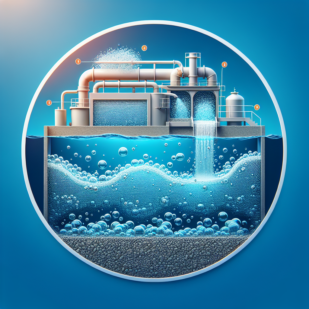
A side stream of clarified effluent is pressurized and brought into contact with air in a saturator, dissolving far more air than the water could hold at atmospheric pressure. When that recycle stream is released through a nozzle or needle valve into the flotation tank, the pressure drop forces the excess air out of solution as a cloud of very fine bubbles.
Bubble size is the controlling variable. Microbubbles in the tens of microns rise slowly enough to have time to collide with and attach to floc, present a large total surface area for attachment, and do not shear the floc apart on release. Coarse bubbles, of the kind an air sparger produces, rise quickly, contact little, and break up the floc they pass through. Getting fine bubbles requires adequate saturation pressure, adequate contact time in the saturator, and a release device in good condition — and a worn or fouled release nozzle is one of the most common causes of a DAF unit that used to work.
Attachment
Bubbles must adhere to the solids. This is a surface chemistry question, not a hydraulic one: particles with high surface charge repel each other and resist attachment, which is why coagulation is not optional in DAF but integral to it. Coagulation neutralizes charge so that particles can aggregate; flocculation then builds aggregates large enough and open enough in structure to capture bubbles within them. Floc that is dense and compact settles well and floats poorly, which is the essential difference between conditioning for a clarifier and conditioning for DAF.
Rise and Removal
The bubble-floc aggregate has a net density below water and rises to form a float layer. A surface skimmer, either a chain-and-flight or a reciprocating beach scraper, removes the float to a hopper. Because the float layer thickens as it dewaters on the surface, skimming frequency is a real operating variable: skim too often and the removed material is thin and watery, adding load to the solids handling train; skim too infrequently and the layer becomes deep enough to break up and carry over.
Key Design Parameters and Sizing
DAF sizing rests on a smaller set of variables than most unit processes, and three of them are usually the subject of negotiation with the supplier.
- Hydraulic loading rate across the flotation tank surface, which determines whether rising aggregates have time to reach the surface before the flow carries them to the effluent. Conventional DAF operates at modest surface loading; high-rate DAF designs incorporating plate packs or lamellae operate considerably higher by shortening the vertical distance an aggregate must travel. Require the supplier to state the basis for the rate offered.
- Recycle ratio, the fraction of treated flow returned through the saturator, commonly in the range of 5–30% depending on the solids load. Because the air available for attachment is set by the product of the recycle flow and the air concentration in it, a higher solids load requires either a higher recycle ratio or a higher saturation pressure. Recycle also consumes tank capacity, so it must be included in the hydraulic sizing rather than treated as a side stream.
- Saturation pressure, commonly in the range of roughly 2–6 bar. Higher pressure dissolves more air per unit of recycle and generates finer bubbles on release, at higher pump energy. The design point trades recycle flow against pressure for a given mass of air delivered.
- Flocculation detention time ahead of the contact zone, sized to build floc of the right size and structure. Too short and the floc is too small to capture bubbles; too long, or with too much mixing energy, and the floc is dense and reluctant to float.
- Contact zone configuration, where the recycle release and the flocculated influent meet. This zone determines attachment efficiency and is where proprietary designs differ most.
On the layout side, size the float hopper and the sludge pumping to handle the float at its actual solids content rather than a nominal figure, provide adequate access for skimmer maintenance, and plan for the bottom sludge draw-off that every DAF unit needs, because a fraction of the solids always settles regardless of conditioning.
Chemical Conditioning and Optimization
Chemical dose does more to determine DAF performance than any mechanical adjustment available to the operator, and the optimization has a specific character because the goal is flotation rather than settling.
Coagulant and Polymer Selection
Aluminum and iron salts — alum, ferric chloride, and polyaluminum chloride — are the common primary coagulants. Polyaluminum chloride is often preferred in DAF because it works across a wider pH band and consumes less alkalinity, which matters in low-buffer waters. Ferric chloride produces strong, dense floc that is excellent for settling and sometimes less cooperative in flotation. Selection should be tested, not assumed.
Polymer selection follows the same logic. A cationic polymer at low dose often assists charge neutralization; a high molecular weight anionic or nonionic polymer used as a flocculant builds the open floc structure that captures bubbles. Overdosing polymer is the most common conditioning error in DAF: excess polymer produces a large, dense, sticky floc that fouls the plate pack, blinds the skimmer, and floats worse than a properly dosed smaller floc.
Jar Testing for Flotation, Not Settling
A conventional jar test ranks chemical programs by how well the floc settles, which can rank them backwards for DAF. Adapt the protocol:
- Run the coagulant series first at fixed mixing conditions, recording floc formation time and visual floc character — open and fluffy is the target, not dense and granular.
- Hold the selected coagulant dose and run a polymer series, again recording floc structure.
- Assess floatability rather than settleability. A bench flotation column, in which a measured volume of saturated water is released beneath the conditioned sample, is the only way to do this properly. Where no column is available, an approximate reading can be taken from how readily floc rises when air is gently introduced, but a column is worth building.
- Measure supernatant turbidity after flotation, and note the float layer’s apparent solids content, since a program that floats everything into a watery blanket has moved the problem downstream rather than solving it.
pH, temperature, and seasonal influent shifts all change the optimum. Cold water slows floc formation and reduces bubble rise velocity simultaneously, so winter generally needs longer flocculation time and often a different polymer. Re-optimize seasonally rather than annually.
Equipment Configurations
DAF units differ in geometry and in how they shorten the rise path.
- Rectangular conventional DAF. An open rectangular basin with a contact zone at the inlet end and a surface skimmer running the length. Simple, robust, tolerant of variable loading, and the largest footprint per unit of flow. Common in municipal drinking water and larger wastewater installations.
- High-rate plate pack DAF. Inclined plates or lamellae reduce the vertical travel required, permitting substantially higher hydraulic loading in a smaller basin. The trade is sensitivity to conditioning: over-dosed or greasy float fouls the plates, and cleaning access becomes a design requirement rather than an afterthought.
- Skid-mounted packaged DAF. Factory-assembled units complete with saturator, recycle pump, chemical feed, and controls. Fast to install, well suited to industrial applications and to municipal sidestream duties, and constrained to the manufacturer’s standard sizes.
- Circular DAF. A rotating skimmer arrangement in a circular tank, often with a moving inlet and outlet. Mechanically simple and compact in plan for its capacity.
Whichever configuration is selected, specify materials for the wetted parts appropriate to the service — 304 or 316 stainless steel for most municipal duties, with attention to chloride content in industrial applications — and specify instrumentation for recycle flow, saturation pressure, float layer level or skimmer cycle, and effluent turbidity.
Operating Practice and Monitoring
A DAF unit that is running well is dull to watch, and the instruments are what tell you it is still running well.
- Effluent turbidity or suspended solids, continuously where possible, as the primary performance indicator and the earliest warning of a conditioning or air system problem.
- Recycle flow and saturation pressure, both trended. A slow decline in either, or a divergence between them, points to saturator fouling, pump wear, or release device wear before the effluent degrades.
- Skimmer cycle frequency, which should be tuned rather than fixed. Rising frequency without an effluent improvement means the float is being removed too thin.
- Chemical feed rates, metered independently of dilution water so dose per unit flow can actually be calculated.
- Bottom sludge draw, on a schedule. Every DAF unit accumulates settled solids, and a basin that has never been drawn down has lost effective volume.
Maintenance concentrates in four places: the air compressor and saturator internals, the recycle pump and its release nozzles, the skimmer drive and flights, and the chemical feed pumps and their calibration. Of these, the release nozzles are the most commonly neglected and the most consequential, because a fouled nozzle produces coarse bubbles that look like air is being delivered while doing almost no useful work.
Troubleshooting Common Failures
Poor capture and carryover. Work through the chain in order rather than adjusting chemicals first. Verify recycle flow and saturation pressure against design. Inspect a release nozzle for fouling or wear and observe the bubble cloud — it should look like milk, not like champagne. Check hydraulic loading against design, including the recycle contribution. Only then run jar tests on the current influent and revisit conditioning. A methodical sequence finds the cause faster than dose adjustment, which often masks a mechanical problem for weeks.
Float layer that will not thicken, or breaks up. Usually over-dosed polymer producing a floc that traps water, or skimming too frequently. Reduce polymer stepwise and lengthen the skim interval, one variable at a time.
Air system problems. Check for leaks on the saturator and recycle piping, verify compressor delivery and that the saturator is not water-logged or air-starved, and confirm the saturation pressure control is holding setpoint under varying recycle demand. An air-starved saturator delivers water with little dissolved air at full apparent pressure.
Seasonal performance loss. Cold water changes both floc formation kinetics and bubble rise velocity. Expect to lengthen flocculation time, adjust polymer selection, and possibly raise the recycle ratio in winter. A plant that runs one chemical program year-round will underperform for part of the year.
Plate pack blinding in high-rate units. Grease or over-dosed floc accumulating on the lamellae. Address the conditioning, then clean the pack; cleaning alone returns the problem within weeks.
Cost, Lifecycle and Retrofit Considerations
DAF carries higher capital and energy cost than a comparable clarifier and buys three things in return: a much smaller footprint, effective removal of solids that will not settle, and the ability to hit tertiary-quality effluent in a constrained site.
The cost structure is distinctive. Capital covers the basin or skid, the saturator and recycle pumping, the air compressor, chemical feed, and controls — a more equipment-intensive package than a clarifier of similar throughput. Energy is dominated by the recycle pump and compressor and is continuous, unlike a clarifier’s low drive load. Chemical cost is substantial and is not optional; DAF without conditioning does not work, whereas a primary clarifier will function after a fashion without chemicals. Solids handling changes character: DAF float is generally thicker than primary clarifier sludge but is a different material, and downstream dewatering should be evaluated against it rather than assumed.
For a retrofit, the practical checklist is: confirm by pilot that the technology addresses the actual influent problem; verify the hydraulic profile can accommodate the unit without repumping; plan the float and bottom sludge routing, which is where retrofits most often stall; provide for chemical storage and feed, including secondary containment; and write acceptance testing on the plant’s real influent into the procurement, with performance tied to stated influent characteristics rather than to a bare removal percentage.
Comparing DAF to the Alternatives
| Criterion | Dissolved Air Flotation | Primary Sedimentation | Lamella / Plate Clarifier | Membrane Filtration |
|---|---|---|---|---|
| Low-density solids | Excellent — the reason to select it | Poor | Poor to fair | Excellent |
| Footprint | Small | Large | Small | Small |
| Energy use | Moderate to high (recycle and air) | Very low | Low | High |
| Chemical dependence | High — integral to the process | Low to moderate | Moderate | Low to moderate |
| Residual character | Float, generally thicker than primary sludge | Thin primary sludge | Thin sludge | Concentrate or backwash |
| Operator attention | Moderate — conditioning and air system | Low | Low to moderate | Moderate to high |
Cascading is common and often the right answer: coagulation and DAF followed by media filtration, or DAF as pretreatment ahead of membranes to remove the material that would otherwise foul them. The red flags suggesting DAF is not the right tool are a heavy grit or dense inorganic solids load, which settles readily and would be better removed by gravity; a site with no practical means of handling the chemical feed; and an operation without the staff capability to maintain a saturation system.
Frequently Asked Questions
What influent characteristics make DAF a better choice than sedimentation?
Low-density and buoyant material: algae, fats, oils and greases, fibers, and finely divided solids that will not settle in a practical detention time. High turbidity with small particle size and seasonal algal blooms are the classic cases. Where solids are dense and readily settleable, a clarifier does the same job with a fraction of the energy and chemical cost.
What recycle ratios and saturation pressures are typical?
Recycle ratios commonly fall between about 5% and 30% of forward flow, with saturation pressures roughly between 2 and 6 bar. The pairing matters more than either number alone, since what governs performance is the mass of air delivered per unit of solids load. Higher solids loads require more recycle, higher pressure, or both. Include the recycle flow in the hydraulic sizing of the basin.
How should jar tests be run for DAF?
Run coagulant and then polymer series as usual, but evaluate floatability rather than settleability, ideally in a bench flotation column where saturated water is released beneath the conditioned sample. Record floc structure as well as supernatant turbidity: the open, low-density floc that floats well is often the one that settles worst, so a settling-based ranking can select the wrong program.
What metrics indicate a DAF unit is underperforming?
Rising effluent turbidity or suspended solids, increased skimmer frequency without any effluent improvement, an unstable or thin float layer, and persistent carryover. Check recycle flow, saturation pressure, and the appearance of the bubble cloud before adjusting chemical dose, since mechanical causes are common and dose changes will mask them.
Can DAF be retrofitted into a plant with limited footprint?
Often yes, and the small footprint is a primary reason for selecting it. The constraints are usually the hydraulic profile, the routing of float and bottom sludge, and space for chemical storage and feed. Confirm performance by pilot on the actual influent before committing to a full retrofit.
How much does chemical dosing affect the resulting sludge?
Considerably. Conditioning determines floc strength, water content, and how the float behaves in downstream dewatering. Overdosing polymer produces a bulky float with entrained water that increases solids handling load while reducing flotation performance, so the dose that gives the clearest effluent is not always the dose that gives the best overall result.
What maintenance matters most for reliable operation?
Compressor and saturator servicing, recycle pump and release nozzle inspection, skimmer drive and flight condition, and chemical feed pump calibration. Release nozzle condition deserves particular attention: a worn or fouled nozzle produces coarse bubbles while all the pressure and flow instruments read normal.
Where does DAF sit relative to sludge thickening by flotation?
They are the same physics applied to different streams. Flotation thickening concentrates waste activated sludge rather than clarifying a process flow, using the same saturator and recycle arrangement at much higher solids concentration, and it is covered separately under air flotation thickening. For the supplier landscape across both duties, see the review of DAF systems manufacturers.
Conclusion
Key Takeaways
- Select DAF for what will not settle. Algae, fats and greases, fibers, and low-density floc. For dense settleable solids, gravity is cheaper in every respect.
- Bubble size is the controlling variable. Fine bubbles come from adequate saturation pressure, adequate saturator contact, and release devices in good condition. A worn nozzle defeats the whole process silently.
- Conditioning is integral, not auxiliary. DAF without coagulation does not work, and the floc that floats best is not the floc that settles best.
- Test floatability, not settleability. A conventional jar test can rank chemical programs backwards for flotation. Build or borrow a bench flotation column.
- Include recycle in the hydraulic sizing. The recycle stream occupies basin capacity and is part of the surface loading, not a side stream to be ignored.
- Re-optimize seasonally. Cold water slows floc formation and bubble rise together, and a single year-round chemical program will underperform for part of the year.
Dissolved air flotation earns its place where gravity fails, and it is unforgiving of the assumption that it will behave like a clarifier with an air line attached. The process succeeds when the air system, the conditioning, and the hydraulic loading are designed and operated as one thing, and it degrades quietly when any of the three drifts.
For engineers evaluating the technology, the decisive steps are to confirm through piloting on the actual influent that flotation addresses the real separation problem, to write acceptance criteria tied to stated influent characteristics rather than to bare removal percentages, and to ensure the plant has both the instrumentation and the staff capability to keep a saturation system in condition. Where those conditions hold, DAF delivers separation performance in a footprint that no gravity process can match.