
Secondary Clarification in Wastewater: Enhancing Effluent Quality
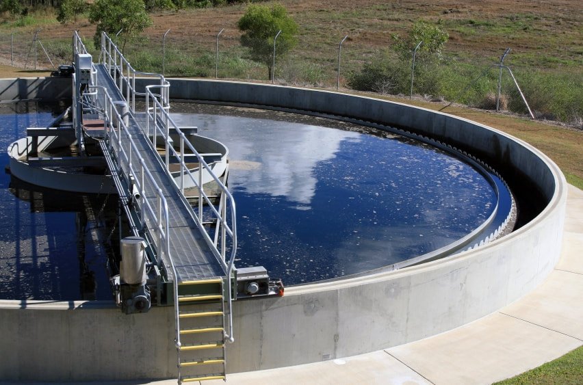
Secondary Clarification in Wastewater Treatment
Secondary clarification is a critical step in wastewater treatment, responsible for separating biological floc or sludge from treated water after primary and biological processes.
This stage determines final effluent clarity before discharge or tertiary treatment. Secondary clarifiers come in multiple designs, each suited to specific operational and spatial needs.
What sets the secondary clarifier apart from every other settling tank in the plant is that it performs two jobs at once. It must clarify, producing an effluent low enough in suspended solids to meet the permit, and it must thicken, returning sludge concentrated enough to sustain the biological process upstream. Those two objectives pull in opposite directions, and the tank must satisfy both simultaneously under every flow and loading condition the plant experiences. Where a unit within primary treatment settles discrete particles whose behavior barely changes week to week, the secondary clarifier settles a living biological blanket whose settling characteristics shift with sludge age, temperature, food-to-microorganism ratio, and the presence of filamentous organisms.
That dependence is why the secondary clarifier is the most common single point of failure in an activated sludge plant. A biological process can be operating perfectly and the plant will still violate its permit if the clarifier cannot hold the solids the process produces. Conversely, most apparent clarifier failures are actually biological problems expressing themselves in the clarifier, which is why diagnosis has to start with the sludge rather than with the tank.
Key Takeaways
- Secondary clarification enhances effluent quality after biological treatment.
- Clarifier design directly affects solids separation efficiency.
- Choosing the correct clarifier type is essential for plant performance.
Fundamentals of Secondary Clarification
Secondary clarification follows biological treatment and focuses on removing activated sludge from the treated wastewater stream.
Principles of Secondary Clarifiers
Secondary clarifiers operate through gravity settling. Flocculated biomass settles to the bottom while clarified water exits from the surface.
Key operational principles include:
- Retention Time: Ensures sufficient settling duration
- Flow Distribution: Prevents turbulence that disrupts settling
- Sludge Removal: Avoids solids carryover
Understanding which settling regime applies is what separates secondary clarifier design from ordinary sedimentation. Four regimes are conventionally recognized, and a secondary clarifier operates in all four at once at different depths. Near the surface, dilute particles settle individually. Below that, particles flocculate as they fall and settle progressively faster. Deeper still, the sludge settles as a mass with a distinct interface, which is zone settling and the regime that governs thickening capacity. At the bottom, the accumulated blanket compresses under its own weight. The behavior of discrete individual particles is covered under settling theory, but it is the zone settling velocity, not discrete particle velocity, that determines how much solids a secondary clarifier can actually handle.
The practical measure of that behavior is the sludge volume index, the volume in millilitres occupied by one gram of sludge after 30 minutes of settling. An SVI below roughly 100 mL/g indicates sludge that settles and compacts well. Values between 100 and 150 are workable but leave less margin. Above 150, filamentous bulking is usually present and clarifier capacity falls sharply, because a bulking sludge occupies far more volume at the same mass and the blanket rises toward the weirs. No amount of clarifier surface area compensates for a badly bulking sludge.
Types of Secondary Clarifiers
Circular Clarifiers
Circular clarifiers feature a central influent feed with radial flow. Settled sludge is collected by rotating scraper arms.
| Feature | Description |
|---|---|
| Design | Circular with central feed |
| Sludge Collection | Rotating scraper arms |
| Flow Pattern | Radial, evenly distributed |
Rectangular Clarifiers
Rectangular clarifiers use a straight flow path and are well suited for high-flow applications.
| Feature | Description |
|---|---|
| Design | Long and narrow |
| Sludge Collection | Flights or rakes |
| Flow Pattern | Linear, inlet to outlet |
Hopper Bottom Clarifiers
Hopper bottom clarifiers feature conical bottoms that promote sludge thickening and easy removal.
| Feature | Description |
|---|---|
| Design | Funnel-shaped bottom |
| Sludge Handling | High concentration removal |
| Efficiency | Excellent for high-settling solids |
Subcategory Overview
The Function of the Secondary Clarifier
Detailed treatment of the function of secondary clarifier in wastewater treatment works through the dual role in operational terms. On the clarification side, the tank must deliver an effluent whose suspended solids concentration satisfies the permit, which for most conventional plants means holding the blanket well below the weirs and preventing short-circuiting or density currents from carrying solids over. On the thickening side, it must deliver return activated sludge at a concentration high enough to maintain the target mixed liquor suspended solids in the aeration basin without returning so much water that the basin’s effective detention time is eroded.
The two functions are coupled through the sludge blanket. A thin blanket clarifies well but returns dilute sludge; a deep blanket thickens well but sits closer to the weirs and risks carryover, and if it goes anoxic it produces rising sludge as denitrification releases nitrogen gas that floats the solids. Operators control this balance through the return activated sludge rate, and getting it right requires measuring blanket depth and RAS concentration rather than running the pumps at a fixed percentage of influent flow. The clarifier is also where the wasting decision is executed, so the same tank governs sludge age and therefore the biological process it serves.
Clarifier Surface Loading Calculator
Checks surface overflow rate against typical design ranges.
Surface Area: ft²
Surface Overflow Rate: gpd/ft²
function toggleFields() { var isCircular = typeEl.value === 'circular'; document.getElementById('circWrap').style.display = isCircular ? '' : 'none'; document.getElementById('rectLenWrap').style.display = isCircular ? 'none' : ''; document.getElementById('rectWidWrap').style.display = isCircular ? 'none' : ''; }
function calculate() { var flow = parseFloat(document.getElementById('flow').value); var area;
if (typeEl.value === 'circular') { var d = parseFloat(document.getElementById('diameter').value); area = Math.PI * Math.pow(d / 2, 2); } else { var l = parseFloat(document.getElementById('length').value); var w = parseFloat(document.getElementById('width').value); area = l * w; }
var warn = document.getElementById('clarWarn'); var results = document.getElementById('clarResults');
if (!isFinite(flow) || !isFinite(area) || flow <= 0 || area <= 0) { results.style.display = 'block'; document.getElementById('clarArea').textContent = '--'; document.getElementById('clarSor').textContent = '--'; warn.textContent = 'Enter a positive flow and positive tank dimensions.'; warn.style.color = '#b00020'; return; } var sor = (flow * 1000000) / area; document.getElementById('clarArea').textContent = area.toFixed(0); document.getElementById('clarSor').textContent = sor.toFixed(0); if (sor > 1200) { warn.textContent = 'Above the typical average-flow range for activated sludge secondary clarifiers (roughly 400 to 800 gpd/ft2, with peak hour commonly limited near 1,200). Check solids loading rate as well.'; warn.style.color = '#b00020'; } else if (sor > 800) { warn.textContent = 'Above the usual average-flow design range but within the band often permitted at peak hour. Verify against the governing state standard and check solids loading rate.'; warn.style.color = '#8a6d00'; } else if (sor < 400) { warn.textContent = 'Below the typical design range. Conservative hydraulically, though solids loading rate and sludge settleability may still govern.'; warn.style.color = '#8a6d00'; } else { warn.textContent = 'Within the typical average-flow design range. Surface overflow rate is only one of two governing criteria; verify solids loading rate before concluding the tank is adequate.'; warn.style.color = '#12683a'; } results.style.display = 'block'; } typeEl.addEventListener('change', toggleFields); btn.addEventListener('click', calculate); toggleFields(); })();
Detailed Analysis of Clarifier Types
Secondary clarifiers vary in design and operational strengths depending on treatment objectives.
Circular Clarifiers
Circular clarifiers allow wastewater to spiral outward from a central feed. Settled solids are scraped toward the center for removal.
Advantages include compact footprint, even hydraulic loading, and reliable sludge removal. These clarifiers are widely used in municipal treatment facilities.
In secondary service the design of the center well matters far more than it does in primary service. A flocculating center well, sized for a short flocculation detention and combined with an energy-dissipating inlet, allows the incoming mixed liquor to aggregate into larger, faster-settling floc before it enters the settling zone. Peripheral baffles at the tank wall, commonly a Stamford or McKinney arrangement, intercept the upward density current that travels along the floor and up the wall and would otherwise deliver solids directly to the weirs. Retrofitting these two features into an existing tank is one of the highest-return upgrades available in secondary clarification.
Rectangular Clarifiers
Rectangular clarifiers are ideal for high-capacity systems. Their linear flow path enables multiple influent points and effective solids removal.
They are often covered to control odors and protect against debris intrusion.
Common-wall construction makes rectangular basins substantially more land-efficient than an equivalent bank of circular tanks, which is why they dominate at very large facilities and on constrained urban sites. The longer travel path also means solids must be conveyed the full length of the tank to the hopper, so flight speed, chain condition, and hopper sizing all bear directly on how promptly sludge leaves the blanket. Multiple withdrawal points along the length are used at larger installations to shorten that path.
Hopper Bottom Clarifiers
Hopper bottom clarifiers feature steeply sloped bottoms that direct sludge toward a central outlet, minimizing accumulation and maintenance needs.
Because the slope moves sludge by gravity alone, these units need no mechanical collector at all, which eliminates the submerged mechanism that accounts for most clarifier maintenance. The trade-off is depth and cost: a hopper steep enough to convey sludge reliably requires a deep excavation, and the geometry does not scale economically to large diameters. The configuration is therefore most common at small plants and package treatment systems.
Solids Contact Clarifiers
Functionality
Solids contact clarifiers combine flocculation and sedimentation in a single unit. Sludge is recirculated to promote particle aggregation.
- Mixing zone: Encourages floc formation
- Settling zone: Allows gravity separation
- Sludge recycling: Enhances efficiency
Applications
- Municipal wastewater treatment with variable loading
- Industrial wastewater with high solids content
The mechanism worth understanding is that recirculated sludge acts as seed material. Incoming particles collide with the far more numerous recycled floc particles rather than only with each other, which raises the collision frequency dramatically and produces larger, denser aggregates than would form otherwise. That is why these units tolerate variable loading better than conventional clarifiers, and why they are widely used in lime softening and chemical precipitation service as well as wastewater.
Lamella Clarifiers and Their Efficiency
Design
Lamella clarifiers use inclined plates to increase effective settling area within a compact footprint.
- Inlet distribution zone
- Inclined settling plates (45–60°)
- Sludge collection hopper
Advantages
- Space-efficient design
- High solids removal efficiency
- Low energy demand
- Scalable for varying flows
The plate angle is a deliberate compromise. Shallower angles present more projected settling area per unit of volume, but below roughly 45 degrees accumulated sludge stops sliding down the plate and fouls it. The 55 to 60 degree range used in most commercial modules is the point at which self-cleaning is reliable. The limitation to understand before specifying lamella modules in secondary service is that the effective area gain assumes solids actually reach and slide off the plates, and a bulking activated sludge with a high SVI will bridge and blind the passages rather than sliding clear. Lamella technology is far better suited to chemically formed floc and primary or tertiary duty than to a clarifier handling a biological blanket of variable quality.
Selection and Specification Framework
Step One: Size on Solids Loading, Not Just Surface Overflow Rate
This is the single most important difference between primary and secondary clarifier design. A secondary clarifier must satisfy two independent criteria, and the more restrictive one governs. Surface overflow rate determines whether the upflow velocity exceeds the settling velocity of the floc, and typical municipal practice uses roughly 400 to 800 gpd/ft² at average flow with peak hour commonly limited near 1,000 to 1,200. Solids loading rate determines whether the tank can thicken the mass of solids arriving, and typical values run about 20 to 30 lb/ft²/day at average conditions and up to roughly 50 at peak. Note that solids loading must be computed on the sum of influent flow and return sludge flow, since both carry solids into the tank. Sizing on surface overflow rate alone is the classic error and produces a tank that clarifies at low load and fails the moment solids inventory rises.
Step Two: Design Around the Sludge You Will Actually Have
Clarifier capacity is a function of sludge settleability, and settleability is a property of the biological process rather than the tank. A plant operating at a long sludge age in cold weather with a filamentous population will present sludge that occupies several times the volume of a well-settling sludge at the same mass. Design should be checked against a realistic worst-case SVI for the process type and climate, not against a nominal value. Solids flux or state point analysis is the appropriate tool, because it evaluates clarifier capacity, RAS rate, and sludge settleability together rather than treating them as independent variables.
Step Three: Provide Depth
Side water depth is the parameter most often shortchanged and the one that most reliably improves performance. Deeper tanks provide volume for the blanket to expand during peak flow and wet weather events without reaching the weirs, and they suppress the density currents that carry solids toward the effluent. Modern practice favors 14 to 16 feet or more for secondary clarifiers, well above the 10 to 12 feet common in older installations. Where an existing shallow tank underperforms, added depth is usually unavailable and baffling becomes the practical substitute.
Step Four: Get the Inlet and the Baffling Right
More secondary clarifier performance is lost to hydraulics than to insufficient area. Specify a flocculating center well with an energy-dissipating inlet so that incoming mixed liquor slows and flocculates before entering the settling zone. Add a peripheral baffle to intercept the wall current. Position weirs inboard of the tank wall rather than on it, where the upward current concentrates. These provisions cost a small fraction of tank construction and routinely deliver more improvement than a capacity increase would.
Step Five: Match the Sludge Withdrawal Mechanism to the Duty
Scraper mechanisms push sludge to a central or end hopper, producing thicker RAS but a longer residence time in the blanket. Suction withdrawal draws sludge across the whole floor simultaneously, giving short and uniform residence time, which matters where denitrification in the blanket would cause rising sludge or where phosphorus release must be avoided in a biological phosphorus removal plant. Hydraulic and riser-pipe arrangements sit between the two. The choice follows from whether the process needs fast, uniform removal or maximum RAS concentration.
Step Six: Compare Against the Alternatives
Where site area is severely limited or the required capacity cannot be achieved by conventional gravity clarification, membrane bioreactors replace the clarifier entirely with a membrane barrier and remove sludge settleability from the equation. Ballasted flocculation and inclined plate modules increase effective capacity within an existing footprint. Understanding how the same equipment behaves on a different duty is useful context, and the comparable design questions for the upstream stage are covered in our guide to primary clarifiers, where sizing rests on surface overflow rate alone and the solids present a far more stable settling behavior.
Comparison Tables
| Configuration | Key Features | Best-Fit Applications | Limitations | Relative Cost | Maintenance Profile |
|---|---|---|---|---|---|
| Circular, center feed | Single center drive; flocculating well and peripheral baffle options | Most municipal activated sludge plants | Less land-efficient in multiples; center well design critical | Low–Moderate | Drive torque monitoring; rake and baffle inspection when dewatered |
| Rectangular | Common-wall construction; multiple withdrawal points possible; easily covered | Very large plants; constrained urban sites; odor control needs | Long sludge travel path; more submerged wear components | Moderate | Chain, flight, and sprocket replacement on a defined interval |
| Hopper bottom | Steep slope conveys sludge by gravity; no collector mechanism | Small plants and package systems | Deep excavation; does not scale economically to large diameters | Moderate at small scale | Minimal mechanical maintenance; hopper bridging is the failure mode |
| Solids contact | Flocculation and settling combined; sludge recirculated as seed | Variable loading; chemical precipitation and softening duty | More complex internal hydraulics; recirculation control required | Moderate | Recirculation equipment plus conventional collector service |
| Lamella / inclined plate | Inclined plates multiply projected settling area | Chemically formed floc; capacity retrofits; primary and tertiary duty | Bulking biological sludge blinds the passages | Moderate–High | Plate cleaning; sludge hopper management |
| Symptom | Usual Cause | Where to Look First |
|---|---|---|
| Blanket rising, solids over the weir | Filamentous bulking raising SVI | Microscopy and SVI trend, not the clarifier |
| Clumps of sludge floating at the surface | Denitrification in the blanket releasing nitrogen gas | Blanket depth and RAS rate; shorten sludge residence in the tank |
| Fine dispersed turbidity, otherwise clear | Pin floc from an over-oxidized, long sludge age process | Sludge age and F:M ratio |
| Dark stable foam on the surface | Nocardioform or Microthrix organisms | Aeration basin surface and selector design |
| Solids over one section of weir only | Short-circuiting, unlevel weir, or density current | Weir survey and dye testing; peripheral baffling |
| Thin RAS with a deep blanket | Withdrawal drawing water through the blanket, or bulking sludge | RAS concentration measurement and SVI |
Design Details and Standards
Sizing Methodology
Establish design average, peak hour, and peak wet weather flows, and the design mixed liquor suspended solids concentration together with the RAS rate range. Compute surface overflow rate on influent flow only, since return sludge is withdrawn from the bottom and does not pass upward through the settling zone. Compute solids loading rate on the sum of influent and return flows multiplied by the MLSS concentration, since both streams carry solids into the tank. Check both criteria at average and peak conditions and take the more restrictive result. Verify the design against a realistic worst-case SVI using solids flux or state point analysis. Then check weir loading rate, set side water depth with allowance for blanket expansion at peak flow, and confirm firm capacity with the largest unit out of service.
Key Parameters
- Surface overflow rate: commonly 400 to 800 gpd/ft² at average flow for conventional activated sludge, with peak hour often limited near 1,000 to 1,200.
- Solids loading rate: typically 20 to 30 lb/ft²/day at average conditions, up to roughly 50 at peak, computed on influent plus RAS flow.
- Side water depth: 14 to 16 feet or more in modern practice; older tanks at 10 to 12 feet are frequently depth-limited.
- Weir loading rate: commonly limited to roughly 10,000 to 30,000 gpd per linear foot depending on plant size and state standard.
- RAS rate: commonly 25 to 100 percent of influent flow, adjusted to hold the target blanket and MLSS.
- Sludge blanket depth: typically maintained in the range of 1 to 3 feet, deep enough to thicken and shallow enough to stay clear of the weirs.
- SVI: below about 100 mL/g indicates good settling; above 150 indicates bulking and materially reduced clarifier capacity.
- Flocculating center well: sized for a short flocculation detention at design flow, with an energy-dissipating inlet.
All values above are typical or approximate design ranges and should be confirmed against the governing state standard, site-specific settleability data, and manufacturer information for the specific mechanism.
Applicable Standards and References
Recommended Standards for Wastewater Facilities, the Ten States Standards, governs surface overflow rate, solids loading, weir loading, side water depth, and redundancy for final settling tanks in many states. WEF Manual of Practice No. 8 and ASCE Manual of Practice No. 76, Design of Municipal Wastewater Treatment Plants, provide the underlying methodology, and WEF's dedicated clarifier design manual covers the hydraulics, baffling, and solids flux analysis in depth. 40 CFR Part 133 establishes the secondary treatment effluent requirements the clarifier must help the plant meet, and 40 CFR Part 122 governs the NPDES permit under which performance is judged. Standard Methods for the Examination of Water and Wastewater defines the sludge volume index and settleability test procedures on which clarifier operation depends. NFPA 820 addresses area classification for covered clarifiers, and OSHA 29 CFR 1910.146 applies to dewatered tank entry with 29 CFR 1910.147 governing lockout and tagout of the collector mechanism.
Specification Checklist
- Design average, peak hour, and peak wet weather flows, with firm capacity stated for the largest unit out of service
- Design MLSS concentration and the RAS rate range
- Surface overflow rate at average and peak, computed on influent flow
- Solids loading rate at average and peak, computed on influent plus RAS flow
- Worst-case SVI assumption and the solids flux or state point analysis supporting the design
- Side water depth, with blanket expansion allowance at peak flow
- Weir loading rate, weir position relative to the tank wall, and levelling tolerance
- Flocculating center well and energy-dissipating inlet specification
- Peripheral baffle type and position
- Sludge withdrawal mechanism type and the process reason for it
- RAS and WAS pumping capacity, turndown, and control strategy
- Sludge blanket depth measurement and its use in control
- Scum collection, pit, and pumping specified as a complete system
- Flow splitting between units, verified across the flow range
- Provision for dewatering and entering a tank while the plant remains in service
Field Notes
Commissioning Considerations
Survey the weirs for levelness with the tank full and flowing, since structural deflection under load moves the launder and a dry survey misses it. Dye test for short-circuiting and density currents: a healthy tank shows a broad, slow arrival at the weirs, while dye reaching one section in a fraction of the theoretical detention time indicates an inlet or baffling problem. Verify the flow split between units by measurement, not by assuming symmetry. Establish baseline settleability with a 30-minute settling test and calculate SVI, and record baseline drive torque with a shallow blanket. Confirm that blanket depth measurement reads correctly against a manual sludge judge.
Common Specification Mistakes
- Sizing on surface overflow rate alone. Solids loading rate governs at higher MLSS and is the criterion that fails when solids inventory rises.
- Omitting RAS flow from the solids loading calculation. Both influent and return streams carry solids into the tank.
- Designing to a nominal SVI. Cold weather and filamentous populations produce SVI values several times the nominal, and the tank must still hold.
- Shortchanging side water depth. Depth buys blanket storage during wet weather and suppresses density currents; it is rarely recoverable later.
- Treating the center well as a hole in the middle. A flocculating well with energy dissipation delivers more capacity than an equivalent spend on additional area.
- Placing weirs on the tank wall. The upward wall current concentrates there and delivers solids straight to the launder.
- Running RAS at a fixed percentage of flow. Blanket depth and RAS concentration are the controlled variables; a fixed ratio guarantees the rate is wrong most of the time.
Operations and Maintenance Comparison
Circular mechanisms concentrate maintenance on the center drive and its torque overload protection, the rake arms, and the baffles, all inspectable only with the tank dewatered. Rectangular chain-and-flight collectors carry far more submerged wear components, and chain, flight, sprocket, and wear strip replacement is a scheduled cost rather than a repair. Suction withdrawal mechanisms shift attention to keeping headers clear and balancing withdrawal across the floor. Hopper bottom units have essentially no mechanism to maintain, trading that advantage for the risk of sludge bridging in the cone. Across all configurations, weir cleaning and levelness checks, scum system upkeep, and blanket depth instrument calibration are the routine tasks whose neglect shows up fastest in effluent quality.
Troubleshooting by Symptom
The governing principle is that most secondary clarifier problems originate in the aeration basin. Solids over the weir with a rising blanket almost always means a settleability problem: run a settling test, calculate SVI, and examine the mixed liquor microscopically before considering anything mechanical. Clumps of sludge floating in patches indicate denitrification in the blanket producing nitrogen gas, addressed by increasing RAS rate to shorten sludge residence in the tank. Fine dispersed turbidity with an otherwise clear effluent is pin floc from an over-oxidized process at excessive sludge age. Solids escaping over one portion of the weir only is hydraulic rather than biological and points to an unlevel weir, a density current, or an uneven flow split. Rising drive torque signals a deepening or denser blanket and should be investigated before the overload trips.
Pro Tip: Trend SVI and Blanket Depth Together
Neither number means much alone, but plotted together they diagnose almost every secondary clarifier complaint. A rising blanket with a stable SVI is a hydraulic or withdrawal problem and belongs to the clarifier. A rising blanket with a rising SVI is a biological problem and belongs to the aeration basin, where no clarifier adjustment will fix it. A deep blanket with a low SVI usually means RAS pumping is simply insufficient. Two measurements taken on every routine round give operators the ability to tell those cases apart in seconds, and they prevent the common and costly pattern of chasing a bulking event with mechanical adjustments for weeks.
Tertiary Treatment Overview
Tertiary treatment follows secondary clarification to further polish wastewater for discharge or reuse.
Secondary vs. Tertiary Treatment
- Secondary Treatment: Biological removal of organic matter (~85%)
- Tertiary Treatment: Advanced removal of nutrients, pathogens, and fine particulates
Tertiary Treatment Technologies
Filtration Methods
- Sand filtration
- Microfiltration membranes
- Activated carbon adsorption
Advanced Processes
- Membrane bioreactors (MBR)
- Ultraviolet disinfection
- Reverse osmosis
- Ozonation
Advantages and Considerations
Benefits
Tertiary treatment produces high-quality effluent suitable for sensitive discharge or reuse.
Economic and Environmental Considerations
While tertiary treatment increases capital and operating costs, it enables water reuse, regulatory compliance, and long-term environmental protection.
Frequently Asked Questions
How does secondary clarification differ from primary clarification in wastewater treatment?
In wastewater treatment, primary clarification primarily targets the removal of solid particulates through sedimentation. On the other hand, secondary clarification occurs after the biological treatment phase, where it separates the bio-floc (biomass) from the treated water using gravity sedimentation as well, but this sedimentation is the result of the biological process, setting them apart functionally and by their point in the treatment sequence.
Can you outline the process involved in secondary clarification for wastewater treatment?
The process involved in secondary clarification typically follows the biological treatment stage. As the mixture of wastewater and activated sludge enters the secondary clarifier, the lower flow velocity allows microorganisms and other solids to settle. Clear, treated water then exits from the top of the secondary clarifier, while the settled biomass is often returned to the aeration tank for further processing.
What functions does a secondary clarifier serve within the wastewater treatment process?
A secondary clarifier serves multiple functions; it not only separates treated wastewater from biological mass but also thickens the sludge by allowing more solids to settle. This thickened sludge can then be recycled back into the aerobic digestion process or moved to sludge processing, which optimizes the treatment process and maintains the efficiency of the biological reactor.
What are the common types of secondary clarifiers used in wastewater treatment plants?
The common types of secondary clarifiers seen in wastewater treatment plants include circular clarifiers and rectangular sedimentation tanks. Circular clarifiers are widely favored due to their efficiency in the even distribution of sludge, while rectangular tanks are often used in larger facilities because they are easier to incorporate into an assembly line process of treatment stages.
Conclusion
Key Takeaways
- The secondary clarifier does two jobs at once — it must clarify to meet the permit and thicken to sustain the biological process, and the design has to satisfy both under every condition.
- Size on solids loading as well as surface overflow rate — solids loading is computed on influent plus RAS flow and is the criterion that fails when solids inventory rises.
- Capacity depends on sludge settleability — SVI is a property of the aeration basin, not the tank, and no amount of surface area compensates for a bulking sludge.
- Depth and baffling beat area — a flocculating center well, a peripheral baffle, and adequate side water depth deliver more improvement per dollar than an equivalent capacity increase.
- Control RAS on blanket depth, not a fixed ratio — a percentage of flow guarantees the withdrawal rate is wrong most of the time.
- Diagnose upstream first — as the function of the secondary clarifier makes clear, most apparent clarifier failures are biological problems expressing themselves in the tank.
Secondary clarification is where the performance of an activated sludge plant is finally measured. Everything the biological process accomplishes is contingent on the clarifier holding the solids it produces, and everything the clarifier can accomplish is contingent on the biology producing sludge that settles. That mutual dependence is the defining characteristic of this unit process and the reason it cannot be designed or operated in isolation.
The approach that works is consistent: size on both governing criteria with RAS flow properly counted, check the design against a realistic worst-case settleability rather than a nominal one, provide depth and hydraulic conditioning rather than area alone, match the withdrawal mechanism to what the process requires of sludge residence time, and operate on measured blanket depth and SVI rather than on fixed pump settings. Plants that trend those two numbers together generally know which side of the process a problem belongs to before they touch anything.