
What Is Sedimentation In Wastewater Treatment
Introduction
Wastewater treatment is a critical component of modern urban and industrial infrastructure, ensuring that the water we release back into the environment is clean and free from harmful pollutants. Sedimentation is one of the oldest and most fundamental processes in the field of wastewater treatment. It serves as a primary mechanism to remove suspended solids from water. This article explores the concept of sedimentation, its importance in wastewater treatment, how it works, its different types, factors affecting its efficiency, and recent advancements in sedimentation technology.
Within primary treatment, sedimentation is unusual in requiring almost nothing: no energy input, no chemicals, and no moving parts beyond a slow sludge scraper. Gravity does the work. That simplicity conceals a design discipline that is more subtle than it appears, because the parameter that governs performance is not the one most people expect.
The Basics of Sedimentation
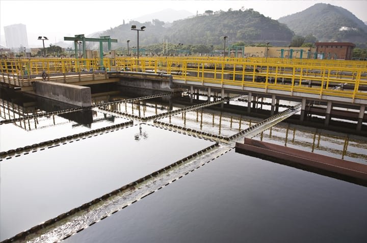
Sedimentation is a physical water treatment process using gravity to remove suspended solids from water. The principle behind sedimentation is based on the natural tendency of particles with higher density than the fluid in which they are suspended to settle by gravity. Sedimentation is used not only in wastewater treatment but also in drinking water purification.
Sedimentation Subcategory Overview
The material beneath this hub covers sedimentation at each stage of the treatment train, its place within primary treatment generally, and the wider principles behind it.
Sedimentation in the Treatment Train
Coverage of primary sedimentation addresses the first settling stage, where raw wastewater is clarified ahead of biological treatment and typically 50 to 70 percent of suspended solids and 25 to 40 percent of biochemical oxygen demand are removed for no energy cost at all. Material on secondary sedimentation addresses the settling stage that follows biological treatment, where the task is entirely different — separating and thickening a flocculent biological sludge that must then be returned to the process. The two stages share a name and a physical principle but have almost nothing else in common, a distinction developed in detail below.
Sedimentation Within Primary Treatment
Two areas place the process in its wider context. Coverage of primary treatment in wastewater addresses the first stage of the treatment train as a whole, and complementary material on primary treatment of wastewater covers the same ground from a process perspective. Sedimentation is the dominant unit process at this stage, which is why primary treatment and primary sedimentation are frequently used interchangeably — though preliminary screening and grit removal precede it and are properly part of the same stage.
Principles and Wider Context
Material on the principles of sedimentation addresses the theory underlying effective water treatment, including the settling regimes and design relationships that determine how a basin performs. Coverage of sedimentation causes and prevention addresses the process as an environmental phenomenon rather than a treatment step — sediment transport into watercourses, its ecological impacts, and the erosion control measures used to prevent it, which is a land management subject rather than a plant operations one. Further afield, material on sediments in the geological record addresses sedimentary deposition over geological time and what it reveals about the Earth’s history — a natural science topic that shares its vocabulary with wastewater treatment but none of its engineering.
Historical Context
The use of sedimentation dates back to ancient civilizations where natural settling ponds were used to clarify water. The modern engineering of sedimentation practices, however, began with the industrial revolution, as urbanization led to increased wastewater production and the necessity for systematic treatment processes.
Importance of Sedimentation in Wastewater Treatment
Sedimentation plays a pivotal role in wastewater treatment for several reasons:
- Reduction of Suspended Solids: It effectively removes the bulk of suspended solids, which can account for up to 65% of the total solids in wastewater.
- Preparation for Further Treatment: By removing solids, sedimentation makes subsequent treatments such as biological treatment more effective by reducing the load on these processes.
- Prevention of System Overloading: Efficient sedimentation prevents overloading of downstream processes, thus extending the lifespan and reducing the operational costs of treatment plants.
- Protection of the Environment: Proper sedimentation reduces environmental pollution by ensuring that solids are not discharged into rivers, lakes, or seas.
Surface Overflow Rate: The Governing Parameter
Sedimentation basin design rests on a result that is counterintuitive the first time it is encountered, and understanding it explains most of what a clarifier looks like.
Why Area Matters and Depth Does Not
In an idealized settling basin, a particle is removed if its settling velocity exceeds the rate at which water rises through the basin — the surface overflow rate, calculated simply as flow divided by surface area. The consequence is that removal efficiency for discretely settling particles depends on surface area alone. Depth does not appear in the relationship at all. A shallow wide basin and a deep narrow one of the same plan area remove the same particles, even though their detention times differ substantially.
A particle is removed if its settling velocity vs ≥ SOR
Q = flow | A = basin surface area | SOR in m³/m²·d
Depth is not irrelevant — it provides sludge storage volume, buffers against turbulence and density currents, and gives the scraper mechanism room to work. But it does not improve the settling of discrete particles, and adding depth to fix a clarifier that is hydraulically overloaded will not help. Adding area will.
Typical Design Values
Primary clarifiers are conventionally designed at surface overflow rates around 30 to 50 cubic metres per square metre per day at average flow, rising to 80 to 120 at peak. Secondary clarifiers following activated sludge operate considerably lower, commonly 16 to 32 at average flow, because the flocculent biological solids they handle settle more slowly and because the clarifier must also thicken them. Weir loading rates typically run 125 to 500 cubic metres per metre of weir per day, and detention times fall around 1.5 to 2.5 hours for primary and 2 to 4 hours for secondary units.
Worked Example: Sizing a Primary Clarifier
Consider a plant treating 10,000 cubic metres per day. At a design surface overflow rate of 40 cubic metres per square metre per day, the required area is 10,000 ÷ 40 = 250 square metres — a circular tank of about 17.8 metres diameter.
Check the other criteria. At a side water depth of 3.5 metres the volume is 875 cubic metres, giving a detention time of about 2.1 hours, comfortably within range. The tank circumference of roughly 56 metres gives a weir loading of 10,000 ÷ 56 = 179 cubic metres per metre per day, also within range. At a peak flow of 2.5 times average, the surface overflow rate rises to 100, which sits inside the acceptable peak band.
Now test the counterintuitive part. Build the same tank at 5 metres deep instead of 3.5. Volume rises to 1,250 cubic metres and detention time to 3.0 hours — but the surface overflow rate is unchanged at 40, so the removal of discretely settling particles is unchanged. The extra depth buys sludge storage and hydraulic stability, not settling performance. Anyone assessing an underperforming clarifier should therefore look at surface loading and hydraulics before considering detention time, which is the figure most often quoted and the least informative. The underlying relationships are developed further under settling theory.
The Process of Sedimentation
Sedimentation is typically employed in the initial stages of wastewater treatment, often after screens and grit chambers remove large debris and sand. The process involves several key stages:
- Collection: Wastewater enters a sedimentation basin or clarifier, where flow velocity decreases, allowing suspended particles to settle.
- Settling: As water remains in the basin, gravity pulls heavier particles to the bottom, forming a layer of sludge.
- Sludge Removal: The collected sludge is periodically or continuously removed from the bottom of the tank for further processing, which may involve dewatering and biological treatment.
- Effluent Discharge: The clarified water at the top is skimmed off and either subjected to further treatment or discharged if it meets environmental standards.
Types of Sedimentation
There are several types of sedimentation processes used in wastewater treatment, each suited to different situations:
- Discrete Sedimentation: Involves the settling of particles that do not flocculate or change in size as they settle. This process typically applies to large particles like sand and grit.
- Flocculant Sedimentation: Particles aggregate to form larger, heavier flocs. This type is common when dealing with biologically or chemically treated water where coagulation and flocculation precede sedimentation.
- Hindered or Zone Sedimentation: Occurs when particles are present in high concentrations, creating a zone where settling is impeded by the presence of other particles. The particulate mass moves as a unit.
- Compression Sedimentation: Takes place when solids concentration is so high that particulate matter at the bottom of the settling zone compacts into a dense layer, pushing water out of the interstices.
These four regimes are conventionally numbered one through four, and knowing which applies is what determines how a basin should be designed. Discrete settling governs grit chambers. Flocculent settling governs primary clarifiers, where particles collide and aggregate as they fall, so removal improves with depth in a way that pure discrete settling does not. Hindered and compression settling govern the lower zones of a secondary clarifier and any thickener. A secondary clarifier is unusual in experiencing three of the four regimes simultaneously at different depths, which is precisely why its design cannot rest on surface overflow rate alone.
Primary and Secondary Sedimentation Are Different Problems
The two stages share a physical principle and very little else, and treating them as variants of one process is a persistent source of confusion.
What Each Is Asked to Do
A primary clarifier receives raw, screened, degritted wastewater and is asked to remove what will settle in a reasonable time. Its performance is measured by how much suspended solids and organic load it keeps out of the biological process downstream, and its sludge is a by-product to be sent to the solids train.
A secondary clarifier receives mixed liquor from the biological process and is asked to do two jobs at once: produce a clear effluent and thicken the settled biomass enough to return it to the reactor at a workable concentration. Failure of either job is a process failure — poor clarification breaches the effluent limit, while poor thickening starves the reactor of the biomass it needs. That dual duty is why primary clarifiers and secondary units are designed against different criteria despite looking similar from the walkway.
Solids Loading Rate
Because a secondary clarifier must thicken as well as clarify, it is checked against solids loading rate — the mass of solids applied per unit of surface area per unit time — in addition to surface overflow rate, and either can govern. Take the same 10,000 cubic metres per day at a secondary surface overflow rate of 24, giving 417 square metres. With mixed liquor at 3,000 mg/L and return sludge at 50 percent of forward flow, the solids applied are 15,000 cubic metres per day times 3 kilograms per cubic metre, or 45,000 kilograms daily — about 108 kilograms per square metre per day, or 4.5 per hour. That falls within the usual range of roughly 4 to 6 kilograms per square metre per hour at average conditions.
The practical point is that a secondary clarifier can be hydraulically adequate and still fail on solids loading, or vice versa. Both must be checked, and which one governs shifts with mixed liquor concentration and return rate — which means a process change made in the aeration basin can overload a clarifier that was previously adequate without any change in flow at all. The broader family of wastewater clarifiers covers the configurations used for each duty.
Factors Affecting Sedimentation Efficiency
Several factors impact the effectiveness of sedimentation in treating wastewater:
- Particle Size and Density: Larger and denser particles settle faster. Fine particles may require coagulation or flocculation to size them up for sedimentation.
- Flow Rates: Higher flow rates can reduce sedimentation efficiency by keeping particles suspended and reducing the time allowed for settling.
- Temperature: Temperature affects water viscosity and density, with warmer temperatures generally enhancing settling velocity.
- Turbulence: Excessive turbulence can re-suspend settled particles, undermining the process.
- Tank Design: Factors such as tank shape, depth, and inlet/outlet design influence sedimentation. Proper design ensures uniform flow and minimizes short-circuiting.
- Chemical Additives: The use of coagulants and flocculants can enhance sedimentation by aggregating smaller particles into larger settling masses.
Density Currents and Short-Circuiting
Two hydraulic effects account for most of the gap between theoretical and actual clarifier performance. Density currents form when incoming water differs in temperature or solids concentration from the tank contents — colder or heavier influent plunges along the floor and can travel most of the tank length before mixing, carrying solids toward the outlet. Short-circuiting is the general case: some water reaches the outlet far faster than the nominal detention time suggests, and it takes solids with it. Well-designed inlet baffles and energy-dissipating inlets exist specifically to convert incoming momentum into gentle distributed flow, and a clarifier underperforming its design values is very often suffering from one of these rather than from insufficient size.
Comparison of Sedimentation Applications
The table below compares the settling duties encountered across a treatment plant. Values are typical or approximate and vary with design standard and local practice.
| Application | Settling Regime | Governing Criterion | Typical SOR (m³/m²·d) | Primary Objective | Main Failure Mode |
|---|---|---|---|---|---|
| Grit chamber | Discrete (Type I) | Velocity control | Not applicable | Remove sand, retain organics | Organics captured with grit |
| Primary clarifier | Discrete and flocculent | Surface overflow rate | 30–50 average; 80–120 peak | Remove settleable solids and BOD | Hydraulic overload; septic sludge |
| Secondary clarifier | Flocculent, hindered, compression | SOR and solids loading rate | 16–32 average | Clarify and thicken biomass | Sludge bulking; blanket carryover |
| Chemical clarifier | Flocculent | Surface overflow rate | Varies with floc quality | Remove chemically formed floc | Poor coagulation upstream |
| Gravity thickener | Hindered and compression | Solids loading rate | Low | Concentrate sludge | Septicity; rising sludge |
| Inclined plate settler | Discrete and flocculent | SOR on projected area | Equivalent basis, small footprint | Clarify within limited space | Blinding; blanket into the pack |
Advances in Sedimentation Technology
While traditional sedimentation relies on gravity, modern advancements have improved its efficiency and adaptability, including:
- Lamella Clarifiers: Use inclined plates to increase surface area for settling, enabling compact designs and improved efficiency.
- High-Rate Settling Tanks: Use mechanical means or chemical additives to enhance settlement speeds and reduce tank size.
- Ballasted Sedimentation: Involves adding micro-sand to increase the weight and size of flocs, allowing faster settling and shorter hydraulic retention times.
- Automation and Monitoring: Advanced sensors and control systems allow real-time monitoring and optimization of sedimentation processes, improving efficiency and response times to changing conditions.
- Hybrid Systems: Combination of physical, chemical, and biological processes in a single system to enhance overall treatment efficiency.
Every one of these works by the same logic: if removal depends on surface area, then either add effective area within the same footprint, as inclined plates do, or increase the settling velocity of the particles, as ballasting and chemical conditioning do. There is no third route. Recognizing that makes the options easy to evaluate — each proposal is answering one of those two questions, and which one it answers determines whether it suits the problem at hand.
Field Notes
Clarifiers underperform in a small number of recognizable ways, and the diagnosis is usually available from data the plant already collects.
Diagnosing a Clarifier
Start with the loading calculations rather than with observation: work out actual surface overflow rate at current average and peak flow, and for a secondary unit the solids loading rate at current mixed liquor and return rate. It is common to find that a clarifier described as failing is simply being operated well outside the conditions it was designed for. If loading is within range, look at hydraulics next — a dye or tracer study reveals short-circuiting and density currents that are invisible from the walkway. For secondary units, measure the sludge volume index and the blanket depth, since bulking sludge and a rising blanket produce carryover that no amount of area corrects. Only after those should the mechanism, weirs, and baffles be suspected.
Pro Tip: Measure the sludge blanket depth on a fixed schedule and trend it alongside effluent solids. In a secondary clarifier the blanket is the single most informative measurement available, and it moves before effluent quality does — a blanket that has been climbing for a week is telling you that solids are entering faster than they are being withdrawn, which gives you days of warning rather than the hours that a turbidity spike allows. A simple core sampler costs almost nothing and turns clarifier operation from reactive into anticipatory.
Common Specification Mistakes
The most frequent error is designing or assessing a clarifier on detention time rather than surface overflow rate, when detention time does not govern discrete settling at all. The second is checking a secondary clarifier against surface overflow rate only, when solids loading rate can govern independently and shifts with mixed liquor concentration. The third is neglecting inlet energy dissipation, which allows density currents and short-circuiting to consume much of the theoretical capacity. The fourth is providing inadequate sludge withdrawal capacity, so that a hydraulically sound tank fails because solids cannot leave it fast enough. The fifth is sizing on average flow without checking the peak condition, which is when clarifiers actually fail.
Common Mistake: Trying to fix an overloaded clarifier by making it deeper. Removal of discretely settling particles depends on surface area, not on depth or detention time, so additional depth adds sludge storage and hydraulic buffering while leaving the fundamental capacity unchanged. If the surface overflow rate is too high, the answers are more surface area, inclined plates to add effective area within the existing footprint, chemical conditioning to raise settling velocity, or flow equalization to reduce the peak. Depth is not on that list, and the fact that it increases detention time is precisely the trap.
Design Details and Standards
Sedimentation basin design is governed by state design criteria and industry manuals rather than by a product standard.
Applicable Standards and References
Design practice draws on the Recommended Standards for Wastewater Facilities (the Ten States Standards), which specify surface overflow rates, weir loading rates, detention times, and side water depths for primary and secondary settling tanks; WEF Manual of Practice No. 8, Design of Water Resource Recovery Facilities; and the WEF and ASCE clarifier design manual, which is the authoritative treatment of settling tank hydraulics, inlet design, and solids flux analysis. Secondary treatment performance requirements derive from 40 CFR Part 133, and effluent obligations from the facility’s NPDES permit. Concrete structures follow ACI 350 for environmental engineering concrete. Analytical methods for suspended solids and settleability follow Standard Methods for the Examination of Water and Wastewater. State primacy agency criteria frequently impose requirements beyond national guidance and should be confirmed before design.
Specification Checklist
- Design flows established at average, maximum month, and peak hour
- Surface overflow rate stated at both average and peak flow, with the design basis referenced
- Surface area derived from surface overflow rate, with depth set separately for storage and stability
- For secondary units, solids loading rate checked at design mixed liquor and return rate
- Governing criterion identified explicitly, since SOR and solids loading can each control
- Weir loading rate within criteria, with weir length and configuration defined
- Side water depth appropriate to the duty and to sludge storage requirements
- Inlet arrangement designed to dissipate energy and distribute flow without short-circuiting
- Density current mitigation considered where influent temperature or solids vary
- Sludge collection mechanism and withdrawal capacity sized against actual solids loading
- Scum collection and removal provided
- Sludge blanket monitoring provision for secondary units
- Redundancy sufficient to maintain treatment with one unit out of service
- Behaviour under peak wet weather flow assessed, not only at average conditions
Environmental and Economic Considerations
Implementing sedimentation in wastewater treatment offers numerous environmental and economic benefits. Environmentally, it maintains ecosystem balance by preventing the discharge of organic and inorganic solids into water bodies. Economically, it reduces the need for potentially expensive downstream treatment processes by removing a significant portion of pollutants early in the treatment train. Effective sludge management and the potential conversion of biosolids into energy or fertilizer further contribute to sustainability and economic viability.
Challenges and Future Directions
Despite its advantages, sedimentation faces challenges such as handling increasing volumes of wastewater, dealing with variable types of pollutants, and complying with stricter environmental regulations. Ongoing research focuses on improving sedimentation technology through innovations like:
- Nanotechnology and Materials Science: Developing new materials that can enhance particle aggregation and settling.
- Data Analytics and Machine Learning: Utilizing data-driven approaches for predictive maintenance and process optimization.
- Integration with Circular Economy Models: Exploring ways to recover and reuse materials from sludge, contributing to sustainable wastewater management.
Frequently Asked Questions
Why does depth not improve settling performance?
Because in an ideal settling basin a particle is removed if its settling velocity exceeds the surface overflow rate, which is flow divided by surface area. Depth does not appear in that relationship. A deeper tank has a longer detention time but the same overflow rate, so it removes the same discretely settling particles. Depth does provide sludge storage, hydraulic buffering, and room for the scraper mechanism, but it will not rescue a clarifier that is hydraulically overloaded.
What is the difference between primary and secondary sedimentation?
Primary sedimentation clarifies raw screened wastewater, removing perhaps 50 to 70 percent of suspended solids and 25 to 40 percent of BOD before biological treatment. Secondary sedimentation follows the biological process and must do two jobs at once — produce a clear effluent and thicken the settled biomass for return to the reactor. That dual duty means secondary clarifiers are checked against solids loading rate as well as surface overflow rate, and either can govern.
My clarifier is failing. Where do I start?
With the loading calculations, not with the tank. Work out the actual surface overflow rate at current average and peak flow, and for a secondary unit the solids loading rate at current mixed liquor concentration and return rate. Clarifiers described as failing are frequently being operated well outside their design conditions. If loading is within range, investigate hydraulics with a tracer study, then sludge settleability and blanket depth, and only then the mechanism.
What are the four settling types and why do they matter?
Discrete settling applies to particles that do not change as they fall, and governs grit removal. Flocculent settling applies where particles collide and aggregate on the way down, and governs primary clarifiers. Hindered or zone settling occurs at high solids concentration where the mass settles as a unit. Compression settling occurs in the dense layer at the bottom. A secondary clarifier experiences three of these simultaneously at different depths, which is why its design cannot rest on surface overflow rate alone.
How do high-rate technologies work?
By one of two routes, and there is no third. Either they add effective settling area within the same footprint, which is what inclined plate and tube settlers do, or they increase the settling velocity of the particles, which is what chemical conditioning and ballasting with micro-sand do. Evaluating any proposal is a matter of identifying which of those two questions it answers and whether that matches the constraint you actually have.
Key Takeaways
- Surface area governs, not depth or detention time — a particle is removed if its settling velocity exceeds flow divided by area, and depth does not enter the relationship.
- Design and assess on surface overflow rate — 30 to 50 m³/m²·d for primary at average flow, 16 to 32 for secondary, checked again at peak.
- Secondary clarifiers have two jobs — clarify and thicken, so solids loading rate must be checked alongside SOR and either can govern.
- A process change upstream can overload a clarifier — raising mixed liquor concentration increases solids loading with no change in flow.
- Hydraulics explain most of the gap between theory and practice — density currents and short-circuiting consume capacity that the calculation says exists.
- Trend the sludge blanket — it moves days before effluent quality does, turning clarifier operation from reactive into anticipatory.
- High-rate options do one of two things — add effective area or raise settling velocity; identify which before evaluating a proposal.
Conclusion
Sedimentation remains a cornerstone of wastewater treatment, providing a reliable, efficient, and cost-effective method to reduce suspended solids. As technology progresses, its integration with advanced processes and materials science holds the promise of even greater efficacy and sustainability in the future. By understanding and optimizing sedimentation, we can continue to protect our water resources and promote environmental stewardship.
The sequence that resolves most clarifier questions is short: calculate the actual surface overflow rate at average and peak flow, add the solids loading rate for any secondary unit, identify which criterion governs, investigate hydraulics before assuming the tank is too small, monitor the sludge blanket as a leading indicator, and remember that if area is the constraint then only area, effective area, or settling velocity will fix it. Approached that way, sedimentation is the most predictable process in the plant — which is why it has survived, essentially unchanged in principle, since the first settling ponds.